Wednesday 7:30 -11:00 am and 9:00 - 10:30 pm
All in all it was a productive day. I printed out 3 stakes, and 4 modified hub guards.
As soon as I came in, I was wanting to print those parts.
I modified the stakes because they needed to be just a little bit thinner so that they could fit length-wise into the holes I had constructed for them.
I modified the hub guards from last time because fit over the rods and the rectangular drum stakes weren't very tight and the hub guards wouldn't have done a very good job at keeping the hub rotating in the hub plate as shown below.
Even though I had made a test holes and pegs with the dimensions and fit that fit as I wanted, once the test holes and pegs were placed together on a hub guard, it didn't fit as tightly as I wanted it to.
Theses were the old ones that didn't fit as tightly as I wanted to

So I slightly adjusted the sizes of the half holes and half rectangles to hold on to the drum stakes and rods better. I did this on Tuesday night, and I had the part as a part and as a DXF.
My partner was supposed to show up at 7:30 am, to work on our project together but she didn't come, so I spent the entire time working on my project alone.
Here is a drawing of my hub guard, in Corel Draw, just before it was sent to the laser cutter.

You know, I thought coming here at 7:30 was rather early since no classes start before 8:30, but in fact, the resident machinist, Larry, was already in by the time I got in to the engineering classroom at 7:30. I helped clean up and set up the laser printer as well as the laser cutting software and the Corel Draw software, which is what opens up the DXF files and sends the cut job over to the laser machine software (called pro-cut) with the correct instructions.
I started printing at 8, but very early on there were a lot of issues with printing my parts.
Firstly I learned not to put cutting lines too close to each other or else the heat around two lines close to each other will be so close as to melt the plastic and create an uneven cut that is either smaller or larger than what you might expect. I'm assuming the detailedness and is what happened to cause the hub cap's holes not to match up with what I might expect from the original solid works drawings and with individual test cuts.
Secondly, I was told to be very aware of any bending in the plastic, which might cause the focus beam of the laser not to be in the middle of the material where it ought to have been .
One of the most obnoxious problems was that the laser printer didn't always cut the entire way through. I mean take a look at this piece, You're supposed to see a gray line indicating where the laser has cut through and separated the material, but for many of the cuts, the middle piece of the plastic is still attached to the outer piece of plastic.
I
actually, I saw a lot of different things about a laser cutter that could affect the cutting.
I saw Larry carefully take out the lens and the mirror that focused the super powerful laser and clean it with lens cleaning fluid and special lens paper that doesn't scratch glass. The mirror was a little cloudy in the center. This might be soot or something else, but it was cleaned.
Larry also played around with thee speed. The default speed for Delrin Plastic was 9 at 2000 bursts [of light] per second but we cut the first one at a speed of 4.5, at default and cut twice. We also tried some other settings for 3/16 Delrin. We also tried decreasing the distance from the laser head to the mateiral in order to change the deph in the material at which the laser beam focused.
Eventually, Larry settled on 7.5 at 1000 bursts per second, cutting multiple times . This made the cleanest cut, but as I had already gotten some serviceable hub plates from the earlier printings, only two of my hub plates had the nice clean cuts of the final cut .
eh blurry image of the laser cutting bed where the material to be cut rests on. The bed has metal deep honeycomb screen that holds the hot material, and the hot laser away from the actual bottom so that it doesn't burn it or warp it from the heat.

All points on the physical bed is directly mapped in to a computer display of the bed in finalcut which is the program that runs the printer.

Unfortunately, there's often the problem that when you cut delrin, you go over it twice or more to make sure it cut through and sometimes if you've been touching the delrin checking to see if the laser cut all the way through, or if your delrin starts bending on you midway through the laser cutting, then some of your lines will have shifted, and then you get a double cut line, or even a triple cut line and at least one of the cuts is not where you want it to be.
here is an example of a double cut line. There's an extra slip of delrin in between the two cuts that I am lifting away from the main piece so that you can see the double cut. Thankfully it wasn't in an area or an edge that was integral to any fits. I can't say that about the other miscut holes in the hub and hubcap (such a pain I say).

After I had all of my pieces printed out finally, I started on putting things together.
This is sanding residue

But here was the result:

This was an interesting way to knock the pegs into the peg holes. Rather than pounding on the top of a long rod, if I pounded really close to the peg with the aid of a stick, then I could more effectively pound the pegs into the peg holes, because less of the hammer force was wasted on deflecting the plastic.

I was very disappointed because some of my laser cut holes came out too small. Even though the measurements were the same across all of the rectangular peg holes in the center hub, somehow, the one pictured below was much smaller than all the others such that when I tried to stick one of the rectangular drum stake


I figured out that I can use clamps to set one side to be in the correct alignment while I whacked away at the other side to make sure the hubs and hubcaps on the other side were in the correct alignment as well.

You know I realized something about the design. I could have dispensed with the central hub all together. I could have made the drun stakes rest directly on the circular hole and spin in there. I was considering usin g
I mean I thought, if I could have 11 stakes, then I'd have a shape of constant width like a Canadian Loonie (explanatory video here). But actually, if you just have the outside surfaces of all of the stakes line up with the inside of the circle, you would effectively have something that could spin circularly but with only however many contact points as you have stakes, which would still be less than an entire circle spinning in a circle.
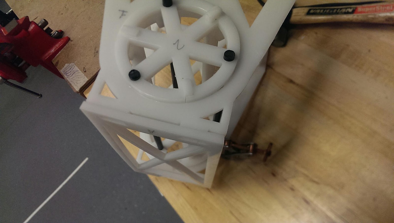
In this image you can see that the hub has a tendency to fall out of the hub plate if not properly aligned. but actually if the hub was completely out of the hole in the hob plate but was still on the stakes holding them in position to be a drum, that could also work.

in our current design, getting the hub to be both at right angles to all of the stakes and simultaneously flush with the hub plate in order for everything to spin smoothly was challenging. I spent a lot of time whacking at hubs in order to get them flush with the hub plates.
Here are some useful tools that I discovered:
Also helpful hint. Use this table vise. This is super useful for sanding corners and edges and holding small parts for you while you fidget with some other tools. Super useful I say. You can't see this in the image but its actually itself clamped to the table and you can unclamp it and move it to any other table with an overhanging lip and start using it at a better location. This is what I did, because I wasn't too chuffed about sanding next to the drill press and the vacuum cleaner.

Also this is a chisel, but its wedge shape is also useful to wedge in between cracks to separate press fitted pieces. Just be careful of its cutting edge.

look it's a small hammer and it fits in through the stakes of my drum just perfectly in order to tap in the middle of my hub, to tap it out! It is great to have and use tools that fit the job. I didn't take a picture, but the big hammers wouldn't have been any use at all to me in this endeavor. Huge hammers are better weapons though, but only if you have that kind of arm strength.

Alas, I feel bad about mentioning this, but a file with no handle is hard to use, and although whoever stuck the big file in a small handle -- I mean I'm no longer stabbing myself in the guts with a pointy object, but its still hard to use.

Amazing details with every part and pictures describing each and every process including cutting, design, and putting the pieces together.
ReplyDeleteI think it's neat how you incorporated a summary of all the tools you used!
ReplyDelete