Monday
This week we were to continue working on our well windlass design. On Monday, we completed a working foam mock up of our design. Initially I was thinking of supports to support the side supports but that would have cost too much building material said the instructor, and so we scrapped that idea, since the side plates were more likely to collapse inward than collapse outward, and our rigid side and top spans should keep the windlass straight and keep the side plates from toppling.
This was the final resulting foam model. There were two side plates that had holes for the hub of the fat drum (alluded to with pencils) to spin in. around both sides of the hub were hub guards to make sure the hub did not pop out of the hole that it was supposed to spin in. The side supports and the top supports were to keep everything at the right angles and keep the side plates from bending in when the force of the water bottle was applied on the center drum. It looks pretty handsome, but didn't know it it would and we knew that it would use too much building material, and we expected to cut a lot of triangles to decrease the material used.

Then we started making the parts in Solidworks
Sorry no pictures at this point, see below for the finished Solidworks parts.
Oh, I should say that I am an very proud of my organization.

FRIDAY
On Friday, we continued making the parts in Solidworks.
The first thing that I worked on was the support spans that would keep our windlass rigid and at a right angle.
I discovered two very neat and useful things about Solidworks as I puzzled over this piece.
One is that you can draw guidlines, that will only be used for construction. When you draw a line, you can select the option that the line you draw will only be for construction purposes.
The other neat discovery was that if you ctrl-click on two or more elements, like lines or points, you can add a relation.
In this manner, I was able to easily create a beautiful X shaped crossbars, shown below. I made a construction line connecting the edges of the space that I wanted to span. Then I made non-construction lines next on either side of the construction line. I selected the three lines, set a parallel relation, and easily noted the distance of each line from the center line.
This was SO much better than the way that I was originally doing it, which was with with a parrallelogram. The parallelogram was difficult and obnixious to to line up, and should I ever choose to change the outer dimensions, because of a lack of relations of a free-drawn parrallelgram, the cross bars would fail to line up anymore

After I created he top supporting span, I created the two supporting support span in solid works in a similar fashion. The picture below shows the extruded finished copy.

Actually, as I seemed to be pressed for material, I reduced the space material that we used by cutting out the cross to make this instead. Because it's a rather small piece, removing the cross structs were unlikely to break it.

IN order to make the drum that holds the string for the windlass, we had to make the rods that made up the skeleton of the drums.
Since all but one of the rods were meant to be of the same shape, I wanted to make cut them all out of the same piece, But alas, when I extruded the whole piece that contained all 6 rods, and then tried to make an drawing of the extruded block containing all 6 rods, the lines that were used to create the rods failed to show up in the drawing. Thus I had to go back and extrude the rods individually and copy them individually into one drawing.
one of the rods that will be the skeleton of the drum that holds the string for the windlass:  I think they were 18 cm even though I could have just gotten away with 16 cm. Maybe I'll make another version of them at 16.5 or 17cm, because that would save me some 5 cm^2
 I think they were 18 cm even though I could have just gotten away with 16 cm. Maybe I'll make another version of them at 16.5 or 17cm, because that would save me some 5 cm^2
After this, all that was left was to do the hub and the side plates. My partner had been working on the side-plates and the hub since Monday. However, I was feeling confident and curious and started tackling the problem of creating a hub. After all I wanted to learn how to arrange things radially in solidworks myself for the future.
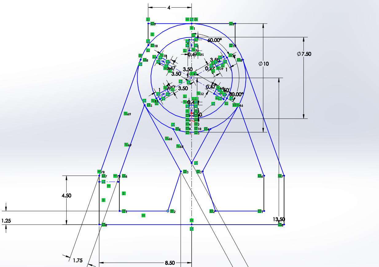
This is the soliworks sketch of the hub that I made. The hub is what holds up the skeleton for creating the drum and would spin in the hole in the side plate.

Oh look all ofthe things are round numbers except for the width of the holes which are about the width of a piece of 3/16in delrin. the .47cm wideth of the holes are actually a little bit smaller than 3/16 in because we wanted a tight fit of the rods into the holes so the rods don't shimmy away as we're pulling the bottle up. Oh a joy, to be in America and have to deal with inches.

For comparison, this is the hub that my partner created. She said she somehow deleted all of the relations, and so I can't be sure if the holes are equally apart around the circle, if they are all equal distances from the center, or if they are all perfectly radially oriented. Additionally, the hub didn't have the pre-specified diameter of 7.5 cm.
We agreed to use my version which had better dimensions and probably better symmetry.

From this hub I created easily created the hub cap by increasing the outer circle's radius, and creating another smaller circle inside, and extruding it differently.


We initially thought of having two different parts for the side plate and the hub, but we were wondering how the hub was going to spin in side the hole of the side plate. I figured that if I cut the internal hub out of the same material as the side plate, it had to fit inside the hole and spin, and if it didn't, well, it would only require a little sanding.
This was my partner's side plate.
I think it looks suspiciously like a Wolkswagen Das Auto award or something.

I used mirroring for the first time to achieve the freehand symmetrical designs
Here are just a few of the relations that I added to my drawing in order to make it pretty and fast and not change unexpectedly when I change one dimension:
tangent, perpendicular, parallel, vertical, horizontal(lines and endpoints), co-linearity,
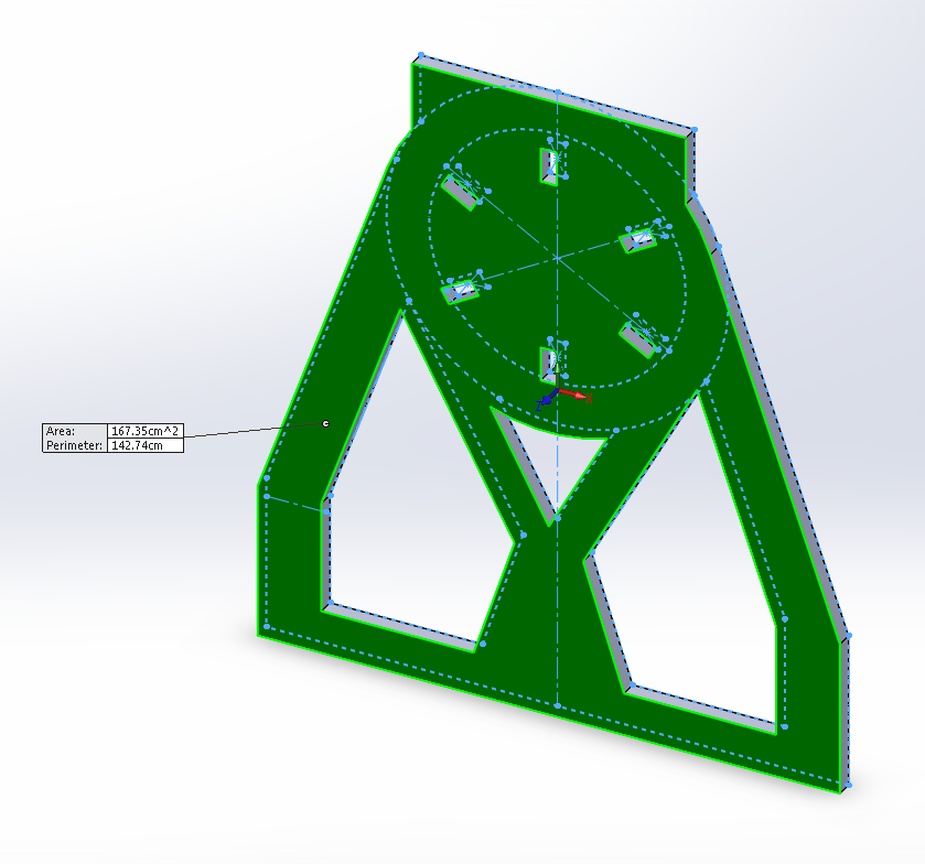
I should mention that I figured out how to get solidworks to measure the surface area of a piece.
What I did was I first extruded the piece, and then under tools, measure, and then click on the face of the part that you want to measure and it automatically tells you the surface area of that surface. Turns out that my design was doing much better on the surface area front. The entire thing was 167 cm^2 which was much better than the 189 something surface area of just the side plate that my partner designed.
all in all, I worked on a lot of files on Friday. Starting from 1:30 all the way until 6:00.
I learned a lot about Solidworks, and in particular about how important and useful relations are!
These are all of the parts and drawings that I worked on during Friday.

You have some amazing detail in your blog! I like all of the pictures from SolidWorks, your parts really come alive!
ReplyDelete