Thursday, April 28, 2016

Final project part 4

Testing the press fit.

On Monday, I tried to use a thermal press to test creating a connection of melted Delrin.  However, a side effect of that is that then there are big protrusions.  This would mean that slide array would be full of knobs, not flush and much thicker than it could be if I had decided to use press fits.
I think that the thickness of the array is important.  Not only would it save material, but also, since it is going to be installed on the inside of a packed cabinet, the less space it takes up, the more convenient it is.

Therefore I decided to use press fit.

I also tested my piece by taping it to a cabinet door to test how easy it is to jostle the toggle out of its correct state.  The good news is that the dips for the dowels are actually deep enough that even a sharp closing or opening will not jostle the toggle out of a set state.   However, the state can be accidentally changed through a sleeve catching on the dowels and changing the state of the toggle.
In order to reduce the chance that that happens, the dowels should be shortened so that they don't stick out as much.

nitpicking problems and my modifications to resolve  them 
1) deciding to do press fits means I need to decrease how much the pins stick out past the holes.   
I measured that pretty much on average the pins stick out about 1mm out from the surface of the front and back. Finally, an instance where the 4th way to measure using a caliper, using the caliper head, the way that many people forget to use.   Then, I decreased how much the pins stick out in  my Solid works model by 1 mm. 

1) spacer gives a little too much space. 
using the caliper, I determined that there is a 6.5mm space for a 3.25mm thick toggle to sit in.  
while I do want to leave some space 
I changed the spacer distance from .65 cm to 0.40 cm or a decrease of 0.25cm 
If this turns out to be too tight, then I can increase the spacer distance to .45 cnm 

2) the connection between back front and spaces was pretty good initially, but it loosened up a bit.  it wasn't so loose that I would feel concerned that it might fall apart accidentally, but I feel like it could be better
it is a pretty good press fit, but I feel like it could be better. 
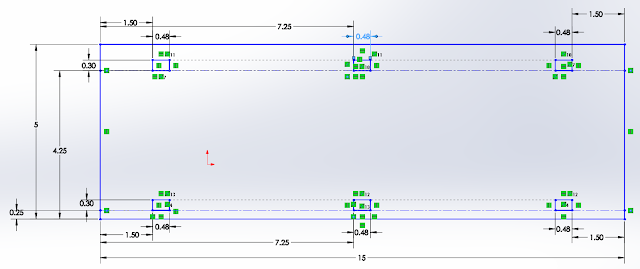
I am putting it 7.25cm from the left.
on the spacer, because the spacer width is 0.4 larger than it was initially, then 
currently the solid works difference between the pin and the hole, or the total allowance (allowance on boths sides) is 0.48cm- 0.7635cm or 0.00375 cm or 0.0375 mm.  after careful examination of the pin hole connection, I figure that I could probably increase the allowance between .3 mm - .4mm.   increasing the current allowance gives something in between 0.3375 - 0.4375mm.  neither those values doesn't divide very nicely by 2 very pretty, and so rather than having an allowance of that I think I will have an total allowance of 0.40mm 
1.50cm = 15.00 mm. thus with a 0.40mm allowance, the pin(on the spacer) should be .4mm or 0.04cm bigger than the hole. 

3) the spacer has a tendency to warp in the up down direction.  
to fix that I am putting in a third connection point in between my two connection points that I had to connect the spacer with the front and back.  in my original design, there are only two connection points for each spacer.  in the new design there are three.   This decreases the length given to the spacer to warp.  this would make the whole structure more rigid. 

4) Given that I was going to put in a third connection point on the spacer, I felt like I could get away with using an even thinner Delrin than a 1/8 in Delrin.  However, after quite a lot of fishing around.  I found that there wasn't enough of the thinner delrin sheets to make my thinner array dream a possibility, and it was unlikely that newly ordered delrin would arrive in time.  Therefore, I stuck with the current thickness of material.  Oh well, at least I know it's very rigid.   

5) I am going to experiment with different length of dowels such that it is still easy to operate but still short enough such that it isn't too easy to bump toggles out of state.

consequently I ended up changing the designs for the front, back and spacers. 


after designing the new pieces, I printed them out and assembled them.  they look very nice. 


on Monday I stayed from 1:30 - 5:30.

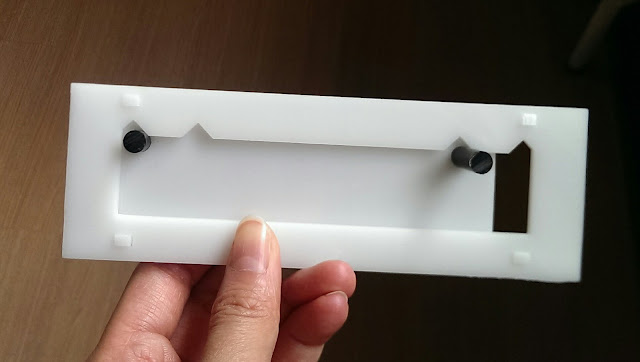
The new version is shown above.  It is thinner.  
The new version is on top.  It is thinner, but it still moves pretty well.  (And it also happens to have toggle upside down)

IN this picture I have tried using different paints and markers to color the back to indicate whether a toy is available or not.  In the top I used a oil-based paint.  on the bottom I used permanent marker.  I think the bottom one looks nicer.  However, with both versions, the back of the toggle is scraping off some of the painted color.  I think maybe I will cover up the colored parts with clear tape to protect the paint from being scraped off, just for aesthetics. 


I also tried to heat stake the dowels, but it didn't work very well because it added significant thicknesses to the toggle, and because I am valuing the thickness of the array, I opted for a tight press fit rather than heat staking all of the dowels.


Final project Part 3

So I had my test pieces printed out and tested!
Spoilers: it worked.   

Before I assess my mechanical toggle, I must mention that saving the Solidworks files into drawings and cutting them out wasn't as easy and straightforward as I expected.  For One I had to remember to extrude the part become I could save part as a drawing.  Additionally, when I saved it, I had to make sure that the drawing was projected frontally in a 1:1 proportion.  I also wanted to make sure that the drawing dimensions fitted the dimensions of the piece.   Also when I saved the drawing, I had to make sure to save it in .DXF format rather than the default Solidworks.  Then I had to transfer ti to the special corel draw software, make sure sure that the dimensions of the drawing of my part matched exactly the dimensions that I had in my solidworks part, and I had to make sure that the size of the document fitted tightly around the part so as not to waste empty space on the actual physical delrin bard later.  I did everything in solidworks in centimeters (like a good scientist), but corel draw was all in inches (like an American designer), which wasn't really a problem at all, but I'm mentioning it anyways.  Then  I had to make sure that all of the lines were hairline lines and were red.  Then I had to print it, setting printer(read laser cutter) preferences to have the small document size that closely encased the part.  Then I had to find the print(read: cut) job in the lasertroc program, and position it.   the other steps of the laser printing process, I think I described earlier, and so I will not repeat myself. 

Well, I got everything printed, and the first iteration almost worked.

The biggest problem was that the toggle was too large for the frame and couldn't move high enough without hitting the internal spacers to allow the dowels to clear the dips.  
In the picture below, I'm holding this up and you can clearly see that the dowels don't clear the dips enough for the toggle to move.
Additionally the hole in the toggle gave the dowels a loose fit.
Also I figured, that I could cut the width of the toggle, because the dowel hole could afford to be closer to the edge, and because I wanted a slightly greater gap in between the toggle and the edge of the window frame in order to better see the color that will eventually be colored in the area in between 
a quick redesign was called for, for decreasing the height and for tightening the dowel holes of the toggle.  
The second iteration is seen above, and the first iteration is seen below
also I re-learned how to use a band saw again.   Honestly I don't mind band saws. They're not as scary as saber saws.  

After the redesign of the toggle, everything else was okay.  The second produced iteration of the toggle fit well with the original iteration of front back and spacer.  The pieces were assembled rather easily and were tight enough that nothing fell apart.  

Another small complaint is that I may have left too much room in between the back and the front for the toggle.  I left that space available because I want it to accommodate the protrusion of the dowel heat staked to the toggle.  I will try to heat stake it and see how much of the empty space, I actually need.


Another small complaint is that the delrin tends to warp and peel away from each other.  I think a third connection point between the spacer and the front and back would ameliorate this situation. 


overall, I 'm pretty satisfied with this second iteration.  everything works.   Now its down to some small tweaks until I'm mostly satisfied.


Here I have a picture of the toggle going from comfortably being on the right to being comfortably on the left.


another small modification:
it is a pretty good press fit, but I feel like it could be better. 

now it was back to the solidworks models to make my modification son the second iteration.  


Friday, April 15, 2016

Final project part 2

On Friday we presented our idea to our client.  We got some good feedback from the child studies center.  

GATHERING SUPPLIES
On Monday we were ready to gather our  materials.
The things that we needed for our project are:
Construction Paper and Post-it notes
delrin sheet
delrin rods
Arduino microcontroller
LED lights
Breadboard
Transistors
RGB LED light strips


Last week, I suggested that rather than using the LEDs that we have in Engineering Lab and dealing with all of the wiring and soldering, that we should get LED light strips, because I saw a rather creative use of microcomputer-controlled LED lights strips to create a light and sound show in a old grandfather clock.
Nanaki was pretty enthused about the labor-saving and cool-ness factor of LED light strips as well.  We wanted to buy LED light strips.  Nanaki looked at light strip prices and options and we wanted to get digital light strips because we wanted a proper light show. 

We submitted our request to order the things that we wanted for our project.


MECHANICAL DESIGN:
When we came up with our current plan, we decided to split up the work into mechanical and electrical/programming.  
Although I'm a CS major, I decided to tackle designing the mechanical aspect because I really enjoyed CAD in Solidworks.   All the construction, relations and dimensions make my pieces perfectly constrained and so beautiful and proper.  *sigh*
Although I expect that both the feedback/control and the mechanical side will have their challenges in design,  The mechanical construction will be much more time-consuming than the electrical/programming portion, due to the plan to heat stake all of the spacers and dowels, which should be around 56 at the very least for just one array.  Still a better deal than soldering twice as much for a button array.  besides it would be much easier to debug.

Frankly, I've been thinking about the mechanical design of the toggle in the window frame ever since I came up with the idea to replace the button toggle 

My toggle mechanism will consist of a back board to hold things together, two dowels attached onto an sliding toggle that can be toggled back and forth, front piece containing a window to the sliding toggle, and a spacer that will prevent the front and back pieces from collapsing together and restricting the movement of the toggle.

On Monday, I made a physical prototype, putting my plotting to cardboard.
This prototype would would only include one window with one toggle good for one toy, so that I could test the design of one window without constructing the whole array which will have lots of 
It confirmed most of my design.  All of the dimension choices look pretty good.  
This is it being slid into the other position:
It moves pretty good.  It reminded me that I had to remember to make the height of the slider from the base of the dowels bigger than the maximum height of the window in the front plate.  
One revelation that I should have seen coming was that the toggle didn't even run on the track because the dowels kept the whole toggle suspended above the track.  Really, I could have imagined in my mind, but alas, good thing for prototypes, eh? 

of course the real thing will have proper spacers and will have little divots that would catch and keep the dowels and thus the toggle in place in the event of an accidental little jolt. 

On Monday I started actually constructing all of the pieces.
Class started at 1: 30 and I didnt' leave until 5:30 because I was on Solidworks creating my designs.
I made a lot of changes to my designs,
I love thinking about and remembering all of the dependencies.   
I have 4 pieces and every time one little thing changes one piece, at least one other thing on another piece needs to be changed. 
In the end I came up with the designs for the back plate, the front plate with the window and the toggle, with space left to insert a Delrin toggle.
It was enjoyable, but it was kinda lonely, because pretty much no one was left in the engineering room after class when I was working on the creating the Solidworks design. 


FRIDAY:  FINISHING DELRIN FINAL PROTOTYPE: 

Friday, I continued thinking about what thickness of Delrin I wanted to use.  Ideally, I would use as thin a Delrin as I could that could remain rigid over around 15 cm.  However another consideration is that the Delrin must be thick enough for me to heat stake the pieces together without too much warping, and as I was looking at the 1/16 Delrin, although it was very thin and looked rigid enough over 15 cm, it looked to be far too thin to heat stake accurately. 

My partner actually suggested 3D printing the front and back boards.  My problem with that was that the array would be around 11" by 11" which would not only be a little too big for the 3d printer, but would use up so much material as to be too expensive.   Additionally, inserting the inside toggle int oa 3d printed front and back when you can't remove the front and back would be a little tricky.  Mostly it was the cost prohibition.

I continued working on my beautiful Delrin designs.  
The back 
spacer
 
toggle, with two hole cutouts for the dowels

front piece

I thought of using construction circles to represent the dowels as they would rest in the divots in the front piece. make it a little more complicated than it otherwise would be, but I think it will be worth it if I ever have to move change the little divots 

Just look at all those relations!  :D
It may be that the little divots aren't deep enough to prevent the dowels from coming out of the divots, but if that proves the case, because the construction with all of the relations between the elements were well thought out, it should be a cinch modifying the depth of the divots, and the window frame.  :D   Wonderful are relations. 


LEARNING TO SOLDER. 
What is soldering?  Soldering is connecting two metal pieces of metal with another metal glob.  Okay, its more refined than that suggests.  you might want to connect two metal pieces, just because you want to connect, them.  Or you might want to connect the two metal pieces together so that an electrical charge can pass through it, and carry power, or a signal or other wonderful things that the flow of electrons can carry.   
In the latter case we use some soldering metal that contained lead to connect two metal pieces together, because, as it happens, lead is a good conductor of electricity, and plus, it has a low melting point, making it easy to melt over the two metal pieces to join them when the lead cools.

This is how you solder.  You get a really hot stick, with a very hot tip, and use it to really heat up the joint, hot enough to melt the solder in the correct way and not hot enough to heat damage the components at the joint.  When you have the joint and the solder stick just hot stick just hot enough, then you press a wire of lead to the joint at the tip of  the hot stick and melt your solder in to a nice neat puddle that you get a nice concave curve connecting the two two pieces which you can get because surface adhesion will give you a concave meniscus. 

One should also exercise good judgement in soldering, like fanning away bad fumes, and being really careful of hot metal sticks.  >.<


Tuesday, April 12, 2016

Final Project: initial thoughts

After visiting the child studies center, a preschool, we came up with a few problems that we thought we could help solve.

The three problems we considered solving were:
1. bathroom locks
2. Keeping track of time
3. keeping track of toys (our final project)

1.
Initially, we were pretty interested in resolving the problem of the bathroom locks.
They weren't very well designed, such that they were rather difficult to open once locked, due to excessive friction.
We wanted to build a different lock that rather than sliding into a hole, would revolve into a holder.
Our solution would have been entirely mechanical, and wouldn't have fulfilled the feedback and control aspect of the final project.  Additionally the mechanical solution is something that should already be on the market, and wouldn't present us with a unique enough challenge for the final project.

2.
The next idea was to help students tackle the problem of keeping track of time.  Preschoolers have a difficult time understanding the concept of time as presented by numbers (which they may not understand) or as presented by a analog clock face (which requires knowing the hand, minute and second in different ways and adding them together to get a time).
Thus I initially thought of generating a linear clock such that would move a marker horizontally across the wall based on how much time as passed.  I thought of powering it with a weight, and and gears that slowly dragged the marker across the wall.   On the wall there would be a ledge and on the ledge there would be colored blocks that could be removed and or reordered that would represent the different activities in the day.   Thinking about it now, I could even put in bells for the marker to push and ring to signal the change of activities.
Like the bathroom locks problem, my solution was entirely mechanical and although it was adjustable, I couldn't really think of how to incorporate feedback and control and electronics into the system.
Additionally there is another team who is tackling this exact same problem and it was better that we worked on a project that was unique from them.

3.
the problem is that the adults need to keep track of which toys are available in a tall cabinet and which toys are out in use and unavailable.
The system that they have now, that they list which toys should be in the cabinet, on the inside of the cabinet door.  the list is covered by a protective plastic sleeve, so it is possible for them to mark the list up with dry erase markers to indicate whether a toy is gone from the cabinet or not.  However, that system involves finding the dry erase markers, uncapping, and recapping them, and is rather slow.  Because the adults want to (and should) get back back to the preschoolers as soon as possible, the system of marking availability with dry erase checkmarks is not used, and the adults still waste time looking for toys where the toys are not.

I initially was going to work with Meba on this problem, but we found that Nanaki was also interested in this problem so we resolved to put each other down as desired team mates and the child studies center as the desired project.  It turned out however, that we were split up, with Nanaki and I forming one group and Meba working with another to form another.

One of the first ideas that we considered, was to have an array of buttons that the adults could click that would set the color of led lights that would indicate whether a toy was in the cabinet or not.
each individual toy would have a label and next to the label, it would have a corresponding button and LED.  When the button was pressed, the LED would toggle between green and red to indicate availability.   The states of all of the LEDs would be remembered by a arduino or similar microcontroller.
Additionally, I thought that we could also double the usage of the LEDs to attract the attention the adults when they open the door of the cabinet.  After all, the child study center did have a system to keep track, but the problem, along with the process taking too long, was that people didn't participate. We could sense the opening of the door through either a light sensor, or a button, or as Nanaki suggested through ultrasound.  Only when we sense the door opening, we could flash the led lights with different patterns to draw the adults attention to the array with the tracking system that they need to remember to fill out.  The pattern would be different each time and that would hopefully keep the the adults from being desensitized to the alert.   As an added bonus, when we sensed that the cabinet door was closed, then we could know to turn off the LEDs in order to save energy.


Upon discussing with our instructor, however, we found that just the soldering of the wires of all  the buttons and LEDs for the hundred toys or so would be such a large task as to be impractically time-consuming for the time given to complete the project.

Thus we went back to the drawing board figuratively and I thought about it hard. I thought about toggles that set a binary state.  I came up with the idea that we could just have sliders that slid back and forth to indicate whether a toy was available or not.

The sliders would have dowel handles attached to them so that you could slide them easily left to right in the space between the window frame and the backing board to indicate the state of the toy.

The dowels would rest on little divots.  These divots will hopefully discourage the slider from accidentally sliding and changing states should the array or the dowels be jolted or nudged.

On the backing board would have the colors green and red to indicate whether the toy is available or not.

Each of the sliders would have a label, that would just be a sticky note or something that the adults can replace should a toy be permanently removed or added to the repository.

I was thinking of making the entire array from Delrin and heat staking to join all of the pieces together.

This system should not be used by young children.  I think children would just find it amusing, and you wouldn't be able to keep the sliders in meaningful states.  Additionally, it has been mentioned that young children would have a hard time mapping the colors to the concept of availability of an item.


Initially, I thought I would have just one large one array, however, after measuring the dimensions of the cabinet for which we are installing, because there is so little clearance between the cabinet door and the ledges in the cabinet, one large array with a thickness more than a few millimeter (which ours will definitely be larger than a few millimeters thick) would be consistently smashed by the ledges and would cause the cabinet doors not to close.  Therefore I changed installing several smaller panels each with their arrays.
I measured the dimensions that were available to me.  For each panel installation, I figured I could comfortably have two columns of sliders and 6 rows.  If I were attempting to be particularly space efficient I could probably still fit in 8 rows to a panel installation.

I am excited to actually start building.


Friday, April 1, 2016

MatLab part 2: modeling thermal systems

This time we are using MatLab to simulate thermal systems like a hot coffee being either heated or cooled.
Interestingly enough, heat transfer can be viewed as an energy transfer not unlike the transfer of electrons.  That helped me remember and understand the thermal dynamics functions better, although I'm still not at the level of comfort where I can just name exactly the units without some thinking

Exercise 1:
given the code to simulate the cooling of coffee. We were than told to determine how varying the parameters Rth and C would effect cooling. Rth is the rate of heat transfer and C is the heat capacity of the thing we're studying.  From Newton's Law of Cooling function, I expect Rth and C to be inversely proportional to the rise in temperature.

Here is the code for the...
% Simulation of cooling coffee
% coffee_coolsim.m
C = 1000; % heat capacity
Tair = 293; % ambient temperature in K (C + 273 = K)
Rth = .85; % thermal resistance
T = 357; % initial coffee temperature in K (84 C)
t = 0; % starting time
tmax = 1500; % duration of simulation
dt = 10; % time step
clf
clc
hold on
axis([0 tmax Tair T])
xlabel ('time (seconds)') % axes labels
ylabel ('temperature (K)')
while t < tmax
    dE = -((T - Tair) / Rth) * dt;
    dT = dE / C;
    T = T + dT;
    t = t + dt;
    plot(t,T,'ro')
    drawnow
end

When we tested, we found decreasing the values of thermal resistance, Rth and heat capacity, C, would increase the rate at which the "coffee" wood cool down.

Rth = 0.85 C = 1000


Rth = .85 C= 500

Rth = .5 C=500


exercise 2
this exercise simulated heating up coffee from room temperature.
below is the code for the simulation.  Note that the difference between this code and the previous code is that now there is an element of power that is providing heat to the coffee system to increase the temperature of the coffee.

Here is the code for the:
% Simulation of heating coffee
% heatsim.m
C = 800; % heat capacity
Tair = 293; % ambient temperature
Rth = 0.80; % thermal resistance
T = Tair; % initial coffee temperature
t = 0; % starting time
tmax = 2000; % duration of simulation
dt = 10; % time step
P = 64/0.85; % power added by heater
clf % clear old figure
clc % clear command center
hold on
axis([0 tmax Tair (T + 100)])
xlabel ('time (seconds)') % axes labels
ylabel ('temperature (K)')
while t < tmax
dE_in = P * dt;
dE_out = ((T - Tair) / Rth) * dt;
dE= dE_in - dE_out;
dT = dE / C;
T = T + dT;
t = t + dt;
plot(t,T,'ro')
drawnow
end

C = 1000 Rth = .64 P= 64


Excercise 2 Part b:
part b of the problem was to guess the parameters of C and Rth from looking at a plot of the data.

In order to find Rth, we looked at the equation P = ΔT / Rth. By isolating Rth, we were left with ΔT / P on the other side. Plugging in the values for ΔT (357-293) and Rth (75), we calculated a Rth of .84.

In order to find C, we looked at the special circumstance of t = 0. When t = 0, for a short duration of dt, we have the equation dT/dt = P/C because we can assume the difference between the temperature of the cup and the temperature of the surroundings is negligible/really close to zero. Isolating C, we get P/(dt/dT). dt/dT is also known as the slope of the equation and can be determined by eyeballing the slope at t=0. The slope, therefore, will vary person by person. I personally think it looks like it is approximately, 20 / 250. This then gives me a value of approximately 950 for C.

exercise 3:


%%

exercise 4:


%%


exercise 5:


Matlab

We're learning Matlab!  Matlab is a popular programming lanaguage in academia.  It is a fancy calculator, but it can also program models and parse data other such things.  I might need to use this programming later.

Here are the things that I programmed with it.

Fibonacci1 Script

% this computes the nth fibonacci number through straightforward 
% mathmatical formula
% precondtion: must assign a value to n before running 
% post condition: the result is stored in ans 

(1/sqrt(5))*( ( (1+sqrt(5))/2 )^n - ((1-sqrt(5))/2)^n )
%this is the translation of the expression that computes the nth fibonacci
%number. its pretty much exactly the same as what you would type in a
%graphing calculator.  The only difference is that we included spaces for
%better readability and debugging.  To run, we set n = 10 and then enter 
%fibonnaci1 into the prompt and it runs the script with n = 10 
%
oh look, Matlab looks like a calculator!


car_update Script

% this is to calculate the number of cars in Albany and Boston if 
% 5% of Albany Cars end up in Boston and 3% of Boston Cars are driven 
% to Boston within a week
% precondition: positive integers set for a and for b 
% postcondition: counts of cars in Albany (a) and in Boston (b)

olda = a % this is to save the old values for albany 
oldb = b % this is to save the old values for Boston 
a = olda + round(0.03*oldb) - round(0.05*olda) % recalclating the new Albany value
b = oldb + round(0.05*olda) - round(0.03*oldb) % recalculating the new Boston value %

car_loop Script

%
%car_loop runs car_update 52 times to simulate the car moving activities
% each week for a year 
%preconditions: positive integers for a and for bb
%postcondition: the number of cars left in Albany is stored in a and the
%number of cars in Boston is stored in b for each week (each time through 
%the loop)  and the last result is the final number of cars at each place.   
for i=1:52   % for weeks 1 through 52, repeat below
    car_update    % call car_update to do calculations for you.  Abstraction.
end 
%

car_loop script with plotting

%car_loop_plot runs car_update 52 times to simulate the car moving activities
%for a year.  Then it plots the change in car values,
%preconditions: must assign a positive integer to a and b
%postcondition: the number of cars left in Albany is stored in a and the
%number of cars in Boston is stored in b for each week (each time through 
%the loop) 

hold on     % hold off on plotting until the very end
for i=1:52    % for weeks 1 through 52, repeat below
    car_update        % calls car_update script to get answer from there
    plot(i, a, 'ro')  % set albany to print in red circles
    plot(i, b, 'bd')  % set boston to printin blue diamonds
end %
Setting a= 150 and b = 150:

setting a = 1000 and b = 1000

Fibonacci sequence script
This, unlike the last one, uses loops to calculate the Fibonacci numbers.  This is an introduction to loops.

% this is another way of doing Fibonacci but using loops
% precondition: set n which is the nth element of the fibonacci sequence
% postcondition: will return the fibonacci sequence up to the nth element
% Note: this does not work for n < 3
prev1 = 1;  % this is the previous fib n-1
prev2 = 1;  % fib n-2

F = prev1   % prints out 1st element of fib seq
F = prev2   % prints out 2nd element of fib seq 

for i = 3:n  % for fib from 3 to n 
    F = prev1 + prev2   % calculate current fib from previous fibs
    prev2 = prev1;      % shift old fib(n-2) to be fib(n-1)
    prev1 = F;          % shift old fib(n-1) to be F
end
%

plotting Fibonacci ratios

% this plots the ratio between the previous and current fibonacci numbers
% precondition: set n to be fibonacci sequence up to the nth fibonacci number 
% postcondtion: get a plot of the Fibonacci ratios and the nth fibonacci number
% F is a vector of fib numbers
% R is a vector of fib ratios
F(1) = 1    % first fib number set to be 1 
F(2) = 1    % second fib number set to be 1
hold on     % holds off on printing the graph until the en d
R(2) = 1    % the ratio R(2) is F(2)/F(1)
plot(2, R(2), 'ro-')  % plot the first ratio in red circles
for i=3:n    % for fib fron 3 to n 
    F(i) = F(i-1) + F(i-2)  % calculate fib from prev fibs
    R(i) = F(i)/F(i-1)      % calculate ratios
    plot(i, R(i), 'ro-')    % plot ratio in red circles
end

ans = F(n)   % oh yeah and return answer
%

setting n = 50, getting

setting n = 100

as you can see, the ratio tends towards one number


simulating best trajectory angle:
to find the best angle to get the farthest distance, I cycled through all of the reasonable angles and for the result of each fire at that angle, I decide whether to update my maximizing angle value based on whether the new distnace achieved exceeds the previous farthest distance achieved.


%
    % Model of trajectory of hit baseball. Assumes no air drag.

    % What angle maximizes the distance travelled?
maxing_angle = 0; 
max_dist = 0;
 for a = 0:90    
    
    clf % clear the previous figure

    hold on % allow plotting of multiple figures

    angle = a; % angle baseball hit, in degrees

    velocity = 50 % initial velocity of baseball, in meters/sec

    rads = angle * pi / 180;

    velocity_x(1) = velocity * cos(rads); % horizontal velocity of baseball

    velocity_y(1) = velocity * sin(rads); % vertical velocity of baseball

    x(1) = 0; % x position of batter

    y(1) = 1; % assume baseball hit 1 meter off ground

    dt = 0.1; % time step for simulation, in seconds

    g = 9.8; % gravitational constant, in meters/sec^2

    i = 1 % iteration index

    while y(i) > 0

    x(i+1) = x(i) + velocity_x(i)*dt; % Update x position

    y(i+1) = y(i) + velocity_y(i)*dt; % Update y position

    velocity_y(i+1) = velocity_y(i) - g*dt; % y velocity changes due to gravity

    velocity_x(i+1) = velocity_x(i); % x velocity doesn't change (assume no air drag)

    plot(x(i), y(i), 'r.-'); % display a red dot for each point, and connect them with lines

    i = i + 1; % change index for next iteration

    end

    final_dist = x(i) % Display the final x value.
    if max_dist <= final_dist
        max_dist = final_dist;
        maxing_angle = a;
    end
 end
 ans = maxing_angle
 %


some peculiarities of Matlab
indexing starts at 1 like math and Julia and not like Python or Java or C.
1:5 prints out 1 2 3 4 5, including the 5 and not 1 2 3 4 like in Python.
(4+3)(3-2) does not work because it is missing the *    it should be (4+3)*(3-2)
exponents are simply 3^2 like in math, not exp(3,2) like in Python
I think Julia is going after Matlab.  I want to see Julia become more popular.

Also, I'm so excited that bash is coming to Windows!